Digital
Dental Workflow
SLM 3D Printing in Dental Applications
The Complete Dental Digital Workflow by 2onelab
Selective Laser Melting (SLM) 3D printing has revolutionized dental applications by enabling the precise and efficient production of high-quality applications, such as RPDs, crowns, and bridges. The process consists of three key steps: pre-processing, processing, and post-processing, which we will explain below.
Pre-Processing
1. Scanning the Model
“Scanning the Model in the Dental Laboratory” is a key component for modern dental digital workflows and SLM 3D printing, creating a precise digital model for the printing process. A gypsum model or impression is scanned to generate an accurate digital file.
Learn More About Scanning the Model
Preparation
The model is cleaned to remove contaminants; scanning spray may be applied to reduce reflections.
Placement
The model is positioned in the scanner for optimal visibility; the settings are adjusted for precision and efficiency.
Scanning
Optical or laser-based 3D scanning technology captures the model; multiple passes may be used and stitched together.
Quality Check
The digital model is reviewed for completeness; rescanning or software refinements if needed.
Storage & Archiving
Saved in standard formats (STL, OBJ) for CAD processing and archived for future use.
2. STL File Creation
To create an STL file for 3D metal printing, specialized CAD software like Exocad, 3Shape Dental System, or SilaPart is used to process and export precise digital models.
Learn More About the STL File Creation
Processing
The scanned 3D model is optimized in CAD software (e.g., adding supports, refining thickness, checking geometry).
Adaptation
Printer-specific requirements (detail sizes, surface quality) are considered.
Export
The model is converted into an STL file with a balanced resolution for precision and efficiency.
This ensures the STL file meets all requirements for high-quality SLM 3D printing.
3. STL File Preparation in Our Software 2Build
In 2Build, the STL file will be prepared for the print and processed into G-code, which provides precise instructions for the metal 3D printer.
Learn More About the STL File Preparation
Import & Error Check
The STL file is loaded into the 2Build software and checked for issues (e.g., incomplete geometries, inverted normals), with fixes applied if needed.
Positioning
The model is aligned within the virtual print space to optimize material use, print time, and support structures.
Support Generation
Automatic support structures stabilize overhangs, with manual adjustments possible for efficiency.
Print Parameters
Settings like layer thickness, speed, laser power, and internal structure are configured for optimal printing.
Simulation & Verification
A test run detects potential issues, estimates print time, and ensures stability.
G-code Generation
The finalized instructions are saved and transferred to the 3D printer via network, USB, or other storage.
This streamlined process in 2Build ensures the STL file is optimally prepared for high-quality and precise SLM 3D printing.
Processing
4. Set Up & Printing With Our Metal 3D Printer 2Create
The SLM 3D printer 2Create is set up by configuring the machine, loading metal powder, and adjusting key parameters for a smooth printing process.
Learn More About Setup & Printing With 2Create
Cleaning & Inspection
Residual materials are removed; build platform, powder containers, and filters are cleaned and aligned.
Parameter Configuration
Settings like layer thickness, laser power, and scanning speed are adjusted based on material and model complexity.
Powder Bed Preparation
A thin, even layer of powder is spread to ensure a smooth first print layer.
Final System Check
Gas supply (argon/nitrogen), oxygen levels, filters, and the laser system are inspected.
G-code Import & Validation
The file from 2Build is verified for compatibility before printing begins.
SLM 3D Printing
The machine builds the model layer by layer based on G-code instructions.
This setup ensures precise and high-quality metal printing under controlled conditions.
5. Unloading & Debinding Our Metal 3D Printer 2Create
After printing, the finished part can be removed immediately. There is no need for the machine to cool down, allowing the extraction process to start right away.
Learn More About Unloading & Debinding 2Create
Chamber Venting
The chamber is vented to release any residual protective gas (argon/nitrogen), and pressure is equalized before opening.
Safety Precautions
Care must be taken, as the build platform and surrounding metal powder may still be warm.Settings like layer thickness, laser power, and scanning speed are adjusted based on material and model complexity.
Excess Powder Removal
Powder is vacuumed or brushed off and collected for reuse, minimizing waste.
Initial Inspection
The part is checked for defects such as cracks, deformations, or incomplete sections.
Machine Cleaning
Remaining powder is vacuumed, filters are cleaned, and the machine is inspected to maintain optimal performance for the next job.
This process ensures efficient production and high-quality parts through careful handling and machine maintenance.
Post-Processing
6. Heat Treatment
Heat treatment enhances the mechanical properties of 3D-printed parts by relieving internal stresses from the printing process, improving strength, durability, and structural integrity.
Learn More About Heat Treatment
Purpose
Relieves internal stresses from rapid heating and cooling during 3D printing.
Handling
The printed part and build platform are carefully removed and inspected for any loose powder or debris.
Furnace Setup
The part is placed in a heat treatment furnace with precise temperature control.
Treatment Profiles
The process includes stress relieving (500-650°C) or annealing (higher temperatures for improved ductility).
Temperature Control
The part is heated to the target temperature and held for a specified time to stabilize the material.
Cooling
The part is cooled gradually or via controlled air cooling, depending on desired properties.
This post-process of selective laser melting (SLM) helps preventing warping, cracking, and ensures dimensional stability.
7.1 Bandsaw – Removing the Part
After the heat treatment (or annealing) process, the next step involves removing the part from the build platform and detaching any support structures.
Learn More About Removing the Part
Purpose
After heat treatment, the part is removed from the build platform and support structures are detached. Once cooled, the part is ready for detachment.
Cutting
A specialized saw, such as a bandsaw or wire cutter, is used to separate the part from the platform.
Care
The saw must be set correctly to avoid damaging the part or causing stress that could lead to cracks.
The build platform is often metal, requiring careful cutting to prevent damage to the part.
7.2 Refurbishing the Building Platform
Recycling the building platform after a 3D printing job is essential to maintain print quality and protect machine components: Remove residual material, inspect the surface, check for damage.
Learn More About Refurbishing the Build Platform
Remove Residual Material
After separating the part with a bandsaw, remove any remaining fragments using a disc sander.
Inspect the Surface
Ensure all support structures are gone. Minor unevenness is acceptable—the coater’s rubber will adjust for it.
Check for Damage
Make sure no sharp or leftover elements remain that could harm the coater’s rubber.
Following these steps prepares the platform for safe recycling and reuse.
8. Supports Removal
Once the part is detached from the build platform after SLM printing, the next task is to remove the support structures.
Learn More About Supports Removal
Tools
Cutting tools, such as saws or pliers, or grinding tools are used to remove supports without damaging the part.
Grinding Machine
In some cases, a grinding machine is used to polish off the attachment points, ensuring a smooth finish.
Multiple Stages
The process may involve several stages of cutting, grinding, and polishing, depending on the complexity of the part.
Final Cleaning
The part is cleaned thoroughly to remove any debris before any additional post-processing, such as polishing or coating, is performed.
The part is fully prepared for the final inspection and further use or assembly.
9. Preparing for Polishing
Before the 3D-printed part can be polished, all remaining support structures must be carefully removed and the part should be thoroughly cleaned.
Learn More About Preparing for Polishing
Tools
Use a Dremel or similar tool to refine details and remove excess material.
Cleaning
Clean the part with compressed air or a soft brush to remove dust and grease.
Smooth Surface
Ensure a clean, smooth surface for the best polishing results.
10. Polishing
After the part has been detached from the build platform and the supports have been removed, the next step is polishing the part to achieve a smooth, high-quality surface finish.
Learn More About Polishing
Method
DLyte electrochemical polishing smooths surfaces using an electrolyte solution and electrical current.
Process
Removes material evenly, ideal for complex geometries.
Preparation
The part is cleaned before being placed in the DLyte machine, where settings are optimized.
Benefits
Creates a smooth, corrosion-resistant surface with reduced friction and improved durability.
The final check ensures quality, with optional post-processing like coating or coloring.
Finish
11. Finished Product
The polishing process should have resulted in a smooth and even surface, allowing for optimal alignment with the corresponding areas of the model. The result is a functional, high-quality SLM 3D printed component ready for use.
Download Our Dental Brochure
Download our dental brochure for all the information you need. If you have any questions, don`t hesitate and reach out to our experts.
Dental Brochure
PDF (2,2 MB)
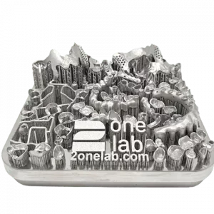
Mixed Plate (CoCr)
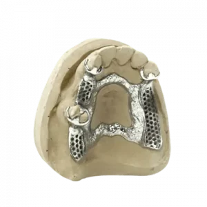
Polished RPD (CoCr)
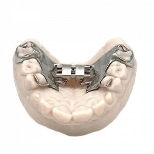
RPE & Welded Expander
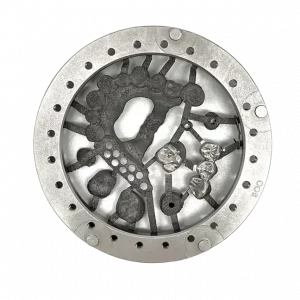
Crowns & Partial Telescope (CoCr)
Success Story
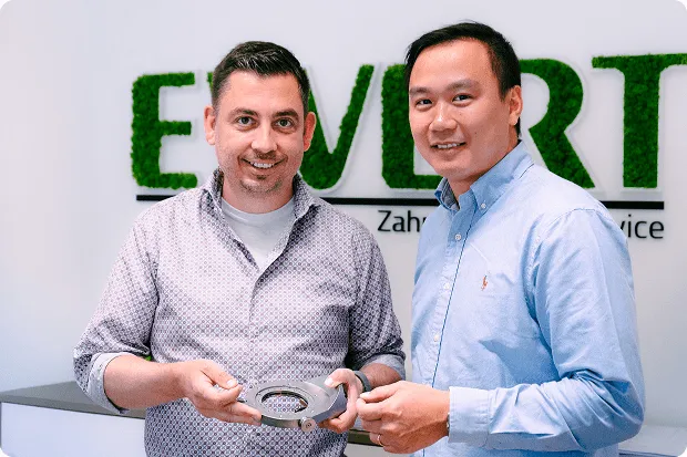
Success Story With Evert Zahntechnik
Digital Hybrid Manufacturing
Learn how Ewert Zahntechnik achieves a precise workflow for high-quality telescopic restorations using the digital hybrid solution from 2onelab and CIMSystem.
We Are Among the Leaders in Dental Metal 3D Printing
Developed and Built in Germany
Tailored metal dental 3D printing solutions with optimized workflows and expert support for faster, precise, and efficient production.
You are here
OVERVIEW
